Typecasting in C: Under the Hood with ARM Cortex-M4 Assembly
What is Typecasting?
There are various sizes and formats in which data can be natively represented in the C language e.g. char, int, float etc.
Often a C program will have to convert (cast) data from one of these types to another. This may be an explicit cast which the user has requested or it may happen implicitly.
I’ve been wanting to dip my feet in ARM assembly for sometime and decided a brief investigation into how the compiler implements type casting would be a gentle introduction.
The Setup
The following GCC command was used to compile most of the examples here:
arm-none-eabi-gcc -std=c99 -O0 \
                  -mcpu=cortex-m4 -mno-thumb-interwork \
                  -mthumb -S
When floating point data types were used the following switch was provided in addition to the above to specify that software floating point should be used:
-mfloat-abi=soft
and when the hardware floating point unit was desired the following switch was specified:
-mfloat-abi=hard
The assembly snippets listed below were generated using the following version of GCC, which was readily available on Debian 8:
arm-none-eabi-gcc (4.8.4-1+11-1) 4.8.4 20141219 (release)
Integer to Integer - A First Glance at Assembly
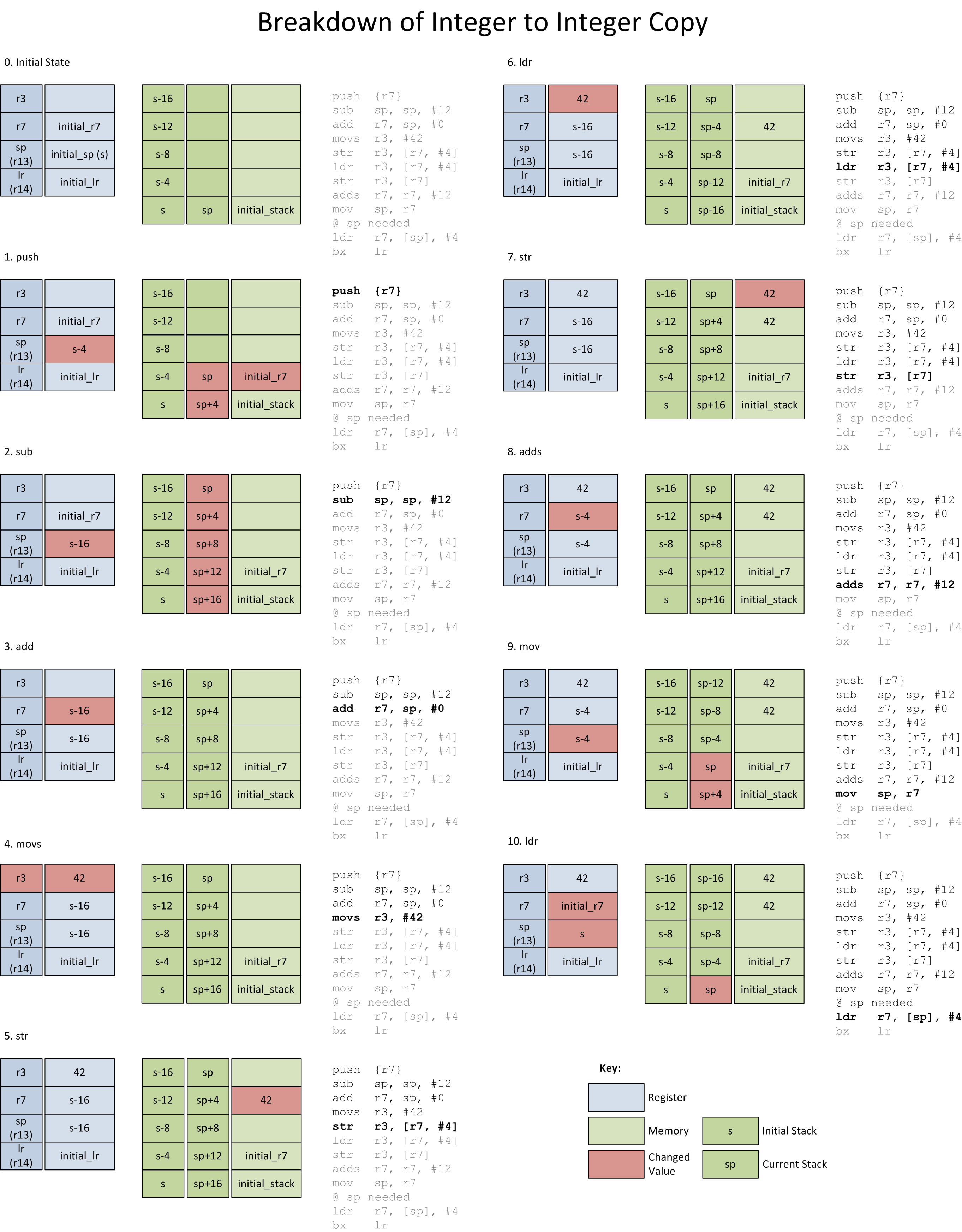
The following (pointless) function simply copies the value of one integer to another.
void test(void)
{
    int x = 42;
    int y = x;
}
This was compiled with the GCC command stated above to generate an assembly listing. The generated assembly can be logically divided into five sequential sections which can be found below.
I wasn’t quite sure what I was expecting, but was a little surprised to find that a significant part of the output was assembler directives rather than instructions (the fact the function is 2 lines long had a lot to do with this). Directives are the keywords which are prefixed with a . and are used to specify various configuration settings to the assembler.
The following links contain more information/documentation on some of the different types of assembler directives:
If you are curious, the following links contain more information on the different types of assembler directives:
1. File Prefix
The first half of the generated assembly file relates to the generated output as a whole. It contains a large listing of assembler directives whose meaning varies from obvious to obscure.
The eabi_attribute directives are some of the more obscure. After briefly decoding a few of them I decided their meanings weren’t relevant enough to bother including here. For those interested, you can refer to section 2.5 of Addenda to, and Errata in, the ABI for the ARM® Architecture (ARM IHI 0045E) where they are referred to as tags.
	.cpu cortex-m4
	.fpu softvfp
	.eabi_attribute 20, 1
	.eabi_attribute 21, 1
	.eabi_attribute 23, 3
	.eabi_attribute 24, 1
	.eabi_attribute 25, 1
	.eabi_attribute 26, 1
	.eabi_attribute 30, 6
	.eabi_attribute 34, 1
	.eabi_attribute 18, 4
	.thumb
	.file	"int_to_int.c"
	.text
2. Subroutine Prefix
Each generated subroutine then has its own set of attributes which precede it:
	.align	2
	.global	test
	.thumb
	.thumb_func
	.type	test, %function
3. Subroutine
At roughly halfway in the assembly file, we reach the more interesting stuff - the generated assembly instructions of the test() function.
test:
	@ args = 0, pretend = 0, frame = 8
	@ frame_needed = 1, uses_anonymous_args = 0
	@ link register save eliminated.
	push	{r7}
	sub	sp, sp, #12
	add	r7, sp, #0
	movs	r3, #42
	str	r3, [r7, #4]
	ldr	r3, [r7, #4]
	str	r3, [r7]
	adds	r7, r7, #12
	mov	sp, r7
	@ sp needed
	ldr	r7, [sp], #4
	bx	lr
The behaviour of this routine is explained below.
4. Subroutine Postfix
The test subroutine ends with the following line:
.size test, .-test
5. File Postfix
The file closes with the .ident directive:
.ident "GCC: (4.8.4-1+11-1) 4.8.4 20141219 (release)"
What is the Subroutine Doing?
The following list and diagram are an instruction by instruction explanation of the subroutines functionality:
- The initial state of things before the subroutine is called.
- r7 is PUSHed onto the stack.
- The stack pointer (sp) is decremented by 12 via SUB. On the Cortex-M4 the stack on grows from high memory addresses to low (a.k.a. “downwards”). Reducing the value of the stack pointer by 12 is in fact allocating room for three 32-bit words.
- The current stack pointer is copied into r7 via an ADD instruction.
- The desired value of the variable
x, 42, is MOVed into register r3. - r3 is stored into the second free word on the stack with STR. This essentially is creating the automatic variable
x. - r3 is loaded with the just written stack variable (42) via LDR.
- r3 (42) is stored (via STR) into the third word on the stack. This is creating the automatic variable,
yfrom thetest()function. At this point all the code from the C function has been implemented in assembly. The rest of the subroutine is cleanup. - r7 is incremented by 12 via ADDS, in preparation to shrink the stack.
- sp is set to the value of r7 via MOV. This is reversing the action of step 2.
- r7 is loaded by reading from the top of the stack. The stack pointer is increased by 4 using LDR with post-indexed addressing which removes a word from the stack, reversing step 1.
- The subroutine exits with BX.
What is going on with r7?
The compiler has used some of the CPU’s precious cycles to ensure the value of r7 is preserved while this subroutine executes. Why does it bother preserving the mysterious contents of this register?
It turns out it’s because the Procedure Call Standard for the ARM® Architecture (ARM IHI 0042) has stipulated as much. This document is part of the ARM ABI (ABI Stack Overflow description) and outlines how compilers should behave in order to enforce some consistency in the compiled code; to allow for the possibility of interoperation. It states:
A subroutine must preserve the contents of the registers r4-r8, r10, r11 and SP (and r9 in PCS variants that designate r9 as v6).
Before the compiler can use r7 as a working register, it must store r7’s current contents somewhere safe - on the stack. Before the subroutine exits, it must also ensure r7 is set back to its initial value. Ensuring that from the perspective of the calling routine it will appear as though nothing has changed.
So why not use one of the other registers which don’t have to be preserved? Again the same document has rules on this:
Typically, the registers r4-r8, r10 and r11 (v1-v5, v7 and v8) are used to hold the values of a routine’s local variables. Of these, only v1-v4 can be used uniformly by the whole Thumb instruction set, but the AAPCS does not require that Thumb code only use those registers.
The first four registers r0-r3 (a1-a4) are used to pass argument values into a subroutine and to return a result value from a function. They may also be used to hold intermediate values within a routine (but, in general, only between subroutine calls).
Presumably GCC is following this recommendation. However, since this function takes no arguments, the compiler should be able to ignore this suggestion and save some cycles by using a register from r0-r3. I would guess it may well do this if optimisation was enabled.
Unnecessary LDR?
You may have noticed the 6th instruction is an LDR which loads r3 from stack memory after just writing r3 to the same location on the stack. I found this behaviour rather peculiar and I haven’t been able to find a valid explanation for it. My guess would be this is a quirk of GCC.
If anyone has any better suggestions as to why this instruction is present, feel free to let me know.
Unsigned / Signed Integer Conversions
Moving onto other type conversions - what should happen during a signed to unsigned, or unsigned to signed integer conversion?
I don’t happen to have a copy of the C99 standard handy, but instead went Googling for answers and found what I assume to be the valid answer on Stack Overflow.
Since ARM processors use two’s complement format to represent negative numbers, when converting between signed and unsigned integers the bit pattern remains unchanged. No additional processing is required, so the generated instructions are identical to the integer to integer example.
The value interpreted from the bit pattern may of course change, for example a negative signed number being converted to an unsigned number will change in value.
Different Sized Data Types
The next focus will be the assembly instructions generated when the output data type is either larger or smaller than the initial data type.
From this point on, only the instructions which are relevant to the conversion will be documented. The initialisation and cleanup of the subroutine should closely resemble the integer to integer conversion that is listed above.
Int to Char
The C source:
void test(void)
{
    int x = 42;
    char y = (char) x;
}
The relevant assembly:
movs    r3, #42
str     r3, [r7, #4]
ldr     r3, [r7, #4]
strb    r3, [r7, #3]
As per the int to int example, there is a store onto the stack followed by a load. However, the setting of the second stack variable, the char y, is achieived through the STRB variant of the STR instruction. The B postfix on STR signifies that only a single byte should be copied. The stack offset specified to store this value is also different from the integer to integer subroutine, with 3 being specified instead of 0.
Char to Int
C source:
void test(void)
{
    char x = 42;
    int y = (int) x;
}
Generated assembly:
movs    r3, #42
strb    r3, [r7, #7]
ldrb    r3, [r7, #7]	@ zero_extendqisi2
str     r3, [r7]
Similar to the int to char example we see the character variable being stored onto the stack via STRB (since the value 42 fits into a single byte). It is re-loaded into register r3 via LTRB. The ARM documentation notes LTRB has the following useful property:
Sizes less than word are zero extended to 32-bits before being written to the register
This ensures that before the second STR saves all 32 bits of r3 to the stack (to create y), the most significant three bytes of r3 are already set to zero.
Floating Point
Floating point numbers have a drastically different binary representation than integers. While some manufactures have their own method of representing floating points, many, including the ARM Cortex-M4F, support the IEEE 754 standard.
Hardware floating point support in the ARM Cortex-M4 line is optional (its inclusion is often denoted by referring to the core as Cortex-M4F). Without this hardware, calculations and conversions involving the float datatype all have to be achieved via software routines. With the hardware, the compiler can make use of floating point instructions to improve performance.
Int to Float
The following is the C source code provided to GCC:
void test(void)
{
    int x = 42;
    float y = (float) x;
}
Hard
We have seen that there are several registers available for data processing. In fact there are 13 standard registers (r0-r12) and 3 special registers (SP, LR, PC). The floating point unit, when present, has its own register bank which contains 32 single precision floating point registers. These are labelled s0 to s31.
Most floating point instructions can only operate on one of these registers, so firstly the FMSR instruction is used to load s14 with the integer to be converted. Once loaded, FSITOS is responsible for the actual converting of the signed integer to a floating point. The instruction FSTS stores the floating point register’s contents onto the stack to create y.
str     r3, [r7, #4]
ldr     r3, [r7, #4]
fmsr    s14, r3      @ int
fsitos  s15, s14
fsts    s15, [r7]
Soft
The integer is loaded into r0, before the subroutine calls out to __aeabi_i2f with BL. Presumably this conversation routine reads r0, converts it to a float then stores the converted value back to r0 before returning.
str    r3, [r7, #4]
ldr    r0, [r7, #4]
bl     __aeabi_i2f
mov    r3, r0
str    r3, [r7]     @ float
Float to Int
void test(void)
{
    float x = 42.424242;
    int y = (int) x;
}
Hard
FLDS loads floating point register s15 from the saved value of x on the stack. This register is converted to a signed integer using FTOSIZS.
FMRS moves the integer to an ARM register to then be written to the stack to represent y.
str        r3, [r7, #4]  @ float
flds       s15, [r7, #4]
ftosizs    s15, s15
fmrs       r3, s15       @ int
str        r3, [r7]
Soft
The subroutine __aeabi_f2iz is used to convert the floating point number contained within r0 into an integer.
str    r3, [r7, #4]    @ float
ldr    r0, [r7, #4]    @ float
bl     __aeabi_f2iz
mov    r3, r0
str    r3, [r7]
Asides
Loading Immediate Negative Numbers
I noticed that the generated assembly was loading negative numbers into a register in a peculiar way.
To investigate in more detail I modified the return value of an otherwise empty function with a handful of low value integers. This was used to produce the table below which shows the desired return value and the corresponding instruction used to load the register.
int function(void)
{
    return 0;
}
| Desired Value | Instruction |
|---|---|
| 3 | mov r0, #3 |
| 2 | mov r0, #2 |
| 1 | mov r0, #1 |
| 0 | mov r0, #0 |
| -1 | mov r0, #-1 |
| -2 | mvn r0, #1 |
| -3 | mvn r0, #2 |
The MOV (and MVN) instructions can take an immediate integer value in the range 0-65535. Immediate values are obtained by reading bits encoded into the instruction’s binary pattern (as opposed to being stored and loaded from a known memory address). The particulars of instruction encodings are documented in ARM®v7-M Architecture Reference Manual (ARM DDI 0403E.b (ID120114)) (to obtain this document ARM requires you to register on their website).
This explains how the values 3,2,1,0 can all be loaded via the MOV command. The values -3 and -2 are outside the available range (0-65535) so cannot be obtained in the same manner. Instead the compiler takes advantage of two’s complement binary representation to allow these numbers to still be encoded as immediate values.
To obtain the correct binary representation of a negative number in two’s complement the following operation is performed:
-X = NOT(X) + 1
Rearranging, with X = -2:
NOT(X) = -X - 1
NOT(-2) = -(-2) - 1
NOT(-2) = 1
The compiler performs this calculation on -2 and provides the output, 1, as the immediate value to the MVN instruction. When executed the destination register is populated with the value of NOT(1) which is the appropriate bit pattern of -2.
But -1 is Also Outside the Range of 0-65535…
…so how can mov r0, #-1 work?
Looking at the possible formats of the MOV instruction, one of them takes a “Operand2” argument which is a “Flexible second operand”. This documentation states this allows the loading of:
any constant of the form 0xXYXYXYXY.
Considering the case where X=F and Y=F we get 0xFFFFFFFF which is the binary representation of -1.
Presumably the compiler performs the logic to check against this encoding before attempting other formats, otherwise it likely would have settled on mvn r0, #0 to give the same result.
Floating Point Mnemonic Changes
At some point ARM updated the mnemonics used for the floating point instructions. The currently used set of instruction mnemonics is called the ARM Unified Assembler Language (UAL). It turns out that the version of GCC I have installed still outputs the older mnemonics. This isn’t a major issue since they all are encoded to the same binary pattern. Annoyingly though, ARM’s Cortex-M4 Instruction Set Summary only documents the newer UAL mnemonics.
I found the following page which provides a mapping between the old ARM mnemonics and the UAL versions. This is not complete however, and ARM has a more detailed reference in section “D2.3 Pre-UAL floating-point instruction mnemonics” of ARM®v7-M Architecture Reference Manual (ARM DDI 0403E.b (ID120114)). This document requires registration on the ARM website to access.
Playing Along at Home
The version of the GCC compiler I used here was part of the development environment I already had set up for STM32’s. However, I recently stumbled across the nifty Compiler Explorer website. It’s aimed more so towards C++, but it allows you to convert C source into assembly from a variety of compilers and compiler versions.